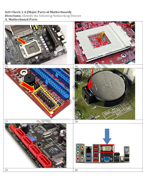
Let us test your memory! Take the quiz in parts identification!

6.7.10
Installing POWER SUPPLY UNIT
Installing POWER SUPPLY UNIT
POWER SUPPLY UNIT is also called as power supply or PSU. This is the device that supplies power to your personal computer. Although you could plug the personal computers directly into standard electrical outlets, the power supply then pulls the required amount of electricity and converts the AC current to DC current and it also regulates the voltage to eliminate spikes and surges common in most electrical systems.
Installing psu| Installing Power Supply Unit | |
 | |
| 1. Position the Power Supply Unit (PSU) into the case as shown above. Screw it from the outside with 4 case screws. | |
 |  |
| 2. Connect the 20 pin motherboard power connector on PSU controller. Its clip snaps when you push it down | 3. New motherboard will require you to connect the 4pin or 8pin 12v motherboard power connector. Connect it and make sure the clip snaps closed to secure the connector. |
| | |
View more presentations from kapitanbasa.
Installing Hard Disk Drive and Optical Drive
Installing Hard Disk Drive and Optical Drive

Installing HDD and Optical Drive
| |
 | |
The image above shows the two types of Internal Hard Disk Drive (HDD): SATA and PATA
| |
 |
1. Note: If you will attach two drives on one IDE rhythm cable, make sure that the hard drive which contains the operating system should be set as master in its jumper setting shown above. Power plug for hard drive is inserted in one way
|
 |
2. Plug the power pins tightly.
|
 |
3. In attaching the IDE rhythm cable, keep in mind that pin 1 of hard drive should be inserted in hole 1 of the IDE cable.
|
 |
4. Attach the IDE thythm cable tightly by pushing it with your tomb finger.
|
 |
5. The orientation of IDE rhythm cable and power pins in hard drive is also the same in optical drives. Just see to it that the jumper setting for optical drive is set to slave.
|
 | ||
Remove the panel from the front of the 5 1/4" drive bay. This could be done by reaching inside and unclipping the side.
Slide the optical drive into the bay. Its front must even with the front of the case. Secure the drive using fine threaded screws. 2 screws for each side
| ||
 |
6. Connect the IDE rhythm cable to the IDE controller of the optical drive. Make sure that pin 1 of IDE rhythm cable should be inserted on pin 1 of optical drive.
| |
 |
7. Push the IDE rhythm cable with your tomb so it will be securely connected.
| |
 |
8. Plug the power connector in the power support of the drive.
| |
 |
9. Make sure it is securely plug.
| |
 |
10. Locate the area that the drive needs to be inserted. Unpack the drive and holding it by its sides, insert it into the drive bay with the rear side (the one with the connectors) facing the motherboard. If your case has side facing drive bays, look into your case's manual to see which direction to insert your drives.
| |
 |
11. Connect the IDE rhythm cable. Make sure you connect pin 1 to hole 1 of IDE cable.
| |
 |
12.Connect the four pins power connector to the hard drive. Line up 4 of the holes in the side of the hard drive with those on the case and secure them with the large threaded screws.
| |
 | ||
13. Your drives setup might be like this shown above. The hard drive is set as master, and optical drive is set to slave using a single IDE rhythm cable.
| ||
 |
14. Attach the IDE rhythm cable in motherboard IDE controller. Push it with your tomb to tighten.
| |
 |
15. Note: Make sure that pin 1 of IDE controller should be inserted in hole 1 of the IDE rhythm cable. Some cable have notch, which you could use as guide in attaching IDE cable in motherboard IDE controller.
| |
 |
16. Make sure that you could identify IDE controller for floppy drive, Optical drive and hard drive and IDE pin 1.
| |
3.7.10
PARTS OF A MOTHERBOARD
MOTHERBOARD
MOTHERBOARD: Also called the "System Board," it is the main printed circuit board in an electronic device, which contains sockets or slots that accept additional boards.
Here are my sample activity worksheets for teachers.
This powerpoint tutorial demonstrate how to install motherboard on a system unit.
You may also read about the parts of the motherboard and challenge yourself by taking the online quiz by clicking the link below:
Parts of the Motherboard
FRONT PANEL CONFIGURATION
Most of my students are afraid to configure the Front Panel because they do not know how they will connect all the Connectors on the motherboard they have. Well it is true that it is not easy and wrong connections might cause damage to your motherboard, so it's important to know exactly where you need to plug each pins before trying to connect them. Here are the things you should do first:
1. Read the motherboard Manual. All motherboard comes with motherboard service manual. On the manual, find the diagrams that will tell you exactly where each set of pins on the motherboard are.
An example of Motherboard manual diagram for Front Panel Header is shown below.
Note: Motherboard Front Panel header Vary so always refer to your motherboard manual.
2. Understand the Front Panel Header Pins. By looking at the pins below your motherboard, you could find the Front Panel Header Pins. So comparing the diagram above, we can say that the next steps will be easy.


Power LED - PWR-LED, P-LED, MSG
MOTHERBOARD: Also called the "System Board," it is the main printed circuit board in an electronic device, which contains sockets or slots that accept additional boards.
INSTALLING MOTHERBOARD
| |
1. Locate the stand outs where you will screw the motherboard
|  |
2. Position the motherboard on the system case.
|  |
3. Make sure the motherboard is position make a note of which holes on the case line up with those on the motherboard.
|  |
1. Once each of the risers is fitted, place the motherboard into the case and line each hole up to the risers. Secure it using the 'fine threaded' screws.
|  |
Here are my sample activity worksheets for teachers.


This powerpoint tutorial demonstrate how to install motherboard on a system unit.
You may also read about the parts of the motherboard and challenge yourself by taking the online quiz by clicking the link below:
Parts of the Motherboard
FRONT PANEL CONFIGURATION
Most of my students are afraid to configure the Front Panel because they do not know how they will connect all the Connectors on the motherboard they have. Well it is true that it is not easy and wrong connections might cause damage to your motherboard, so it's important to know exactly where you need to plug each pins before trying to connect them. Here are the things you should do first:
1. Read the motherboard Manual. All motherboard comes with motherboard service manual. On the manual, find the diagrams that will tell you exactly where each set of pins on the motherboard are.
An example of Motherboard manual diagram for Front Panel Header is shown below.
 |
| Picture taken from Asrock p4v88 Service Manual |
2. Understand the Front Panel Header Pins. By looking at the pins below your motherboard, you could find the Front Panel Header Pins. So comparing the diagram above, we can say that the next steps will be easy.

3. Connect the all the connectors.
Note that the picture above shows that the Front Panel Header comes with shorthand names. This is also printed in all connectors so you will not be confused. For example, in the above picture we can see that the Power Switch Connector should be connected to Pin 6-8 because we can see it on the diagram below

We should insert the Power Switch connector on this way

The front panel header also connect the Power LED the one that lights on the Power button when you boot up the computer.
The Reset Switch,

the Hard Drive activity LED

and the System Warning (beeping) Speaker from the case to the motherboard. Front Panel Header may vary from all motherboard so I listed below some possible shorthand names for these which will be written on the connectors themselves.
Power LED - PWR-LED, P-LED, MSG
Power Switch - PWR-SW, PW SW, PW
Reset Switch - RES-SW, R-SW, RES
Hard Disk Drive LED - HDD-LED, HD
Speaker - SPK, SPKR, SPEAK
Reset Switch - RES-SW, R-SW, RES
Hard Disk Drive LED - HDD-LED, HD
Speaker - SPK, SPKR, SPEAK
2.7.10
How to install memory (RAM)
RANDOM ACCESS MEMORY:


HOW TO GET COMPATIBLE MEMORY ON A SPECIFIC MOTHERBOARD

Method 1: The motherboard manual will give you details about the compatible MEMORY for the motherboard.
 Method 2: Get the motherboard specification
(Manufacturer and Model Name).
Method 2: Get the motherboard specification
(Manufacturer and Model Name).
Motherboard manufacturer and model name can be found at the motherboard box.

You can also get the motherboard specification (Manufacturer and Model Name) using the motherboard manual.
 Most of the motherboard also have
label or sticker attached to it containing about the Manufacturer Name and
Model name.
Most of the motherboard also have
label or sticker attached to it containing about the Manufacturer Name and
Model name.
 Next is to search for the motherboard
manufacturer and model name on its official website. then look for the correct specification or its compatible memory.
Next is to search for the motherboard
manufacturer and model name on its official website. then look for the correct specification or its compatible memory.

The personal computer memory module is a piece of hardware that allows stored data to be accessed randomly. Its main function is to store the data temporarily.
This powerpoint tutorial demonstrate how to install memory.
This powerpoint tutorial demonstrate how to install memory.


Method 1: The motherboard manual will give you details about the compatible MEMORY for the motherboard.

Motherboard manufacturer and model name can be found at the motherboard box.

You can also get the motherboard specification (Manufacturer and Model Name) using the motherboard manual.


How to Install Processor (CPU)
CPU OR CENTRAL PROCESSING UNIT –often define as the brain of computer and the most critical component of a system unit. CPU is responsible for the speed of performance of your computer. A slow processor will always result in a slow computer.
A computer technician must have a wide experience and knowledge about processors. Knowledge about compatible processor for a specific motherboard is very helpful in a computer technician. Here is a simple steps on how to get compatible processor for a specific motherboard.

There are two major manufacturer of personal computer processor:
Knowledge about a PROCESSOR manufacturers and its model name will give a computer technician an information on what motherboard it should be installed.

Step 1: The motherboard manual will give you details about the compatible CPU for the motherboard.

Method 2: Get the motherboard specification (Manufacturer and Model Name). Motherboard manufacturer and model name can be found at the motherboard box.

You can also get the motherboard specification (Manufacturer and Model Name) using the motherboard manual.

Most of the motherboard also have
label or sticker attached to it containing about the Manufacturer Name and
Model name.

After getting the motherboard
manufacturer and model name, access the official website of the motherboard and
look for the correct specification of CPU
of the system board you have in hand.

Installing PGA Processor
| |
 |
1. Match the pins of the CPU to the holes of the CPU support.
|
 |
2. Match the shape formed by the holes from the CPU support to the CPU. This will be one of your guide in installing the CPU
|
 |
3. Position the CPU making sure that all pins will be inserted inside the holes.
|
 |
4. Do not push or force the CPU while inserting all pins on holes. Pins will be inserted smoothly if you position it correctly.
|
 |
5. Secure the CPU by clipping the CPU using the CPU lever lock.
|
 |
6. Install the Heatsink and plug the CPU power connector to the motherboard CPU power controller (Refer to your CPU motherboard manual for this.
|
Subscribe to:
Posts (Atom)