
MOTHERBOARD
MOTHERBOARD: Also called the "System Board," it is the main printed circuit board in an electronic device, which contains sockets or slots that accept additional boards.
Here are my sample activity worksheets for teachers.
This powerpoint tutorial demonstrate how to install motherboard on a system unit.
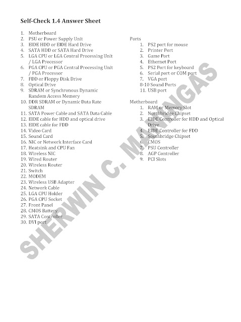
You may also read about the parts of the motherboard and challenge yourself by taking the online quiz by clicking the link below:
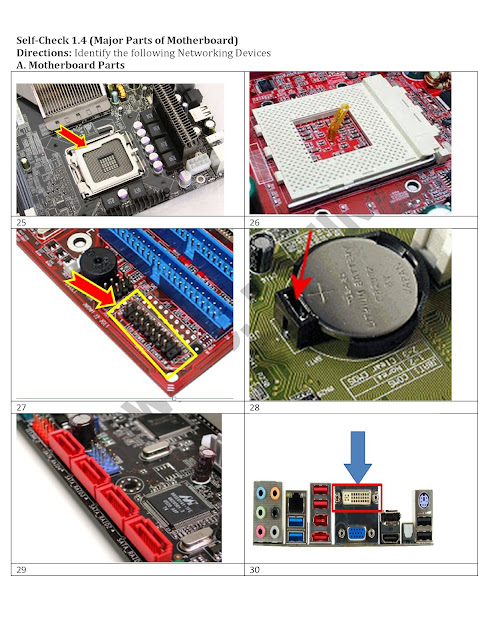
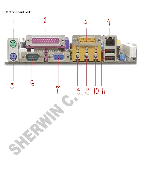
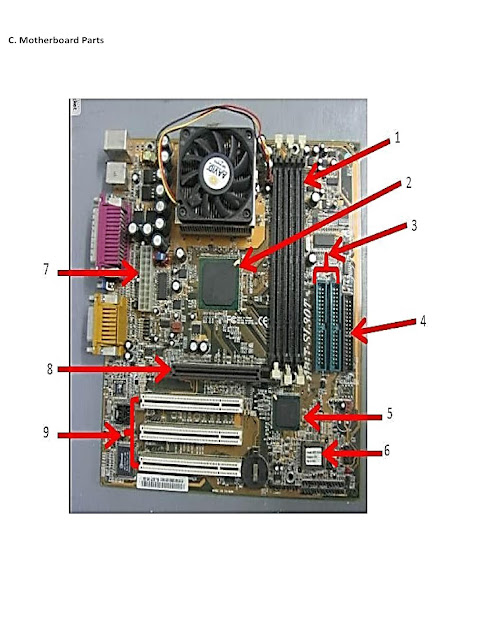
Parts of the Motherboard
FRONT PANEL CONFIGURATION
Most of my students are afraid to configure the Front Panel because they do not know how they will connect all the Connectors on the motherboard they have. Well it is true that it is not easy and wrong connections might cause damage to your motherboard, so it's important to know exactly where you need to plug each pins before trying to connect them. Here are the things you should do first:
1. Read the motherboard Manual. All motherboard comes with motherboard service manual. On the manual, find the diagrams that will tell you exactly where each set of pins on the motherboard are.
An example of Motherboard manual diagram for Front Panel Header is shown below.
Note: Motherboard Front Panel header Vary so always refer to your motherboard manual.
2. Understand the Front Panel Header Pins. By looking at the pins below your motherboard, you could find the Front Panel Header Pins. So comparing the diagram above, we can say that the next steps will be easy.


Power LED - PWR-LED, P-LED, MSG
MOTHERBOARD: Also called the "System Board," it is the main printed circuit board in an electronic device, which contains sockets or slots that accept additional boards.
INSTALLING MOTHERBOARD
| |
1. Locate the stand outs where you will screw the motherboard
|  |
2. Position the motherboard on the system case.
|  |
3. Make sure the motherboard is position make a note of which holes on the case line up with those on the motherboard.
|  |
1. Once each of the risers is fitted, place the motherboard into the case and line each hole up to the risers. Secure it using the 'fine threaded' screws.
|  |
Here are my sample activity worksheets for teachers.


This powerpoint tutorial demonstrate how to install motherboard on a system unit.
You may also read about the parts of the motherboard and challenge yourself by taking the online quiz by clicking the link below:
Parts of the Motherboard
FRONT PANEL CONFIGURATION
Most of my students are afraid to configure the Front Panel because they do not know how they will connect all the Connectors on the motherboard they have. Well it is true that it is not easy and wrong connections might cause damage to your motherboard, so it's important to know exactly where you need to plug each pins before trying to connect them. Here are the things you should do first:
1. Read the motherboard Manual. All motherboard comes with motherboard service manual. On the manual, find the diagrams that will tell you exactly where each set of pins on the motherboard are.
An example of Motherboard manual diagram for Front Panel Header is shown below.
 |
| Picture taken from Asrock p4v88 Service Manual |
2. Understand the Front Panel Header Pins. By looking at the pins below your motherboard, you could find the Front Panel Header Pins. So comparing the diagram above, we can say that the next steps will be easy.

3. Connect the all the connectors.
Note that the picture above shows that the Front Panel Header comes with shorthand names. This is also printed in all connectors so you will not be confused. For example, in the above picture we can see that the Power Switch Connector should be connected to Pin 6-8 because we can see it on the diagram below

We should insert the Power Switch connector on this way

The front panel header also connect the Power LED the one that lights on the Power button when you boot up the computer.
The Reset Switch,

the Hard Drive activity LED

and the System Warning (beeping) Speaker from the case to the motherboard. Front Panel Header may vary from all motherboard so I listed below some possible shorthand names for these which will be written on the connectors themselves.
Power LED - PWR-LED, P-LED, MSG
Power Switch - PWR-SW, PW SW, PW
Reset Switch - RES-SW, R-SW, RES
Hard Disk Drive LED - HDD-LED, HD
Speaker - SPK, SPKR, SPEAK
Reset Switch - RES-SW, R-SW, RES
Hard Disk Drive LED - HDD-LED, HD
Speaker - SPK, SPKR, SPEAK
ok to sir.............
ReplyDeleteYou explained all these things so perfectly...A very good effort, best blog to get some info. about motherboard...Keep this sharing going...
ReplyDelete.asp file
DANTE THE SAILOR MAN
ReplyDeleteTanks for information
ReplyDeleteHow to change motherboard on pc
This is aawesome
ReplyDelete